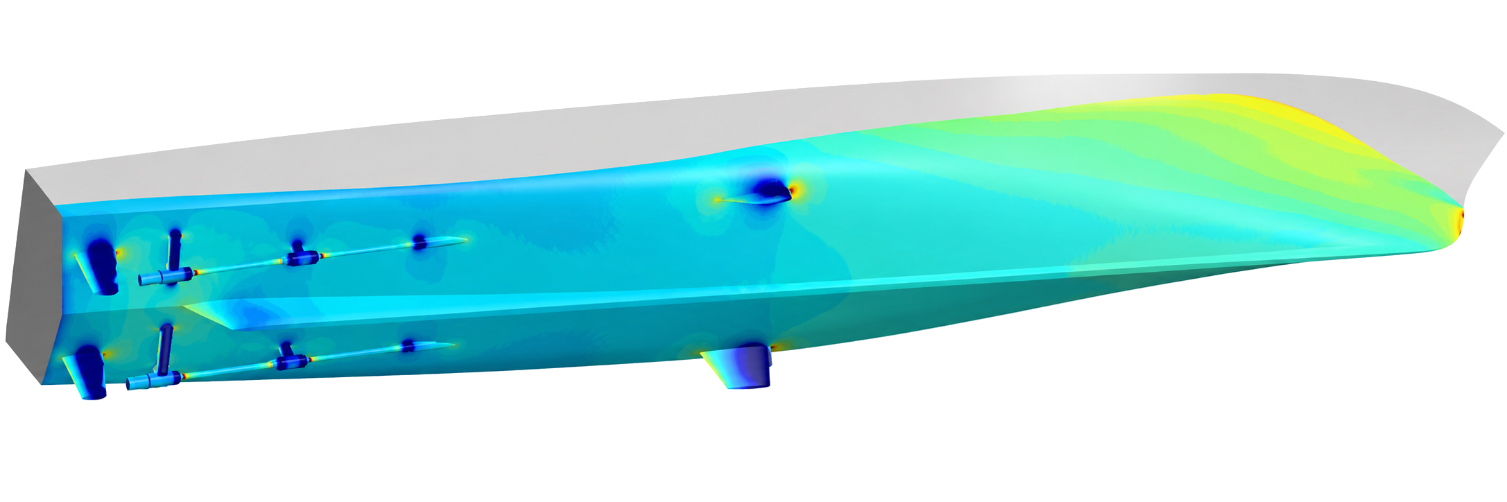
A defense prime is developing an improved offshore patrol vessel to reach higher speeds. The current as-built patrol vessel reaches 24.7 knots with two main engines delivering a combined 5,920 kW. With the same installed power, the defense prime aims to reach 27 knots or more, requiring coordinated optimization of the hull and appendages to reduce total resistance. Figure 1 illustrates a generic offshore patrol vessel.
Conventional Computational Fluid Dynamics (CFD) simulations make this design search inherently sparse. Each new hull and appendage configuration must be generated, meshed, simulated with full-scale multiphase CFD, checked for convergence, and post-processed. A single simulation can take days. An optimization that demands hundreds of operating points is therefore often reduced to tens of cases and can extend over months.
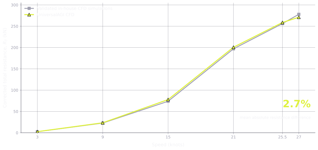
The defense prime is rethinking that workflow by adopting the UniversalAGI Physics AI platform. Our Simulation Factory generated patrol vessel variants within the shipyard's design constraints, preserving the aft hull and propulsion-line arrangement while varying the forward fairlines and bulbous-bow designs. It then orchestrated the high-fidelity CFD campaign across low to high Froude-number regimes, with the resulting simulations showing a reported 2.7% mean absolute resistance difference from the defense prime's validated reference CFD results.
Those simulations fine tuned Ship-PT, UniversalAGI's state-of-the-art foundation model for ship hydrodynamics, to the patrol vessel design space. The resulting vessel-specific model returns calm-water resistance and full hydrodynamic flow fields in a reported median of 2.6 seconds. The defense prime is bringing an AI-native approach to hull design, turning hydrodynamic insight into faster exploration, faster learning, and earlier design decisions.
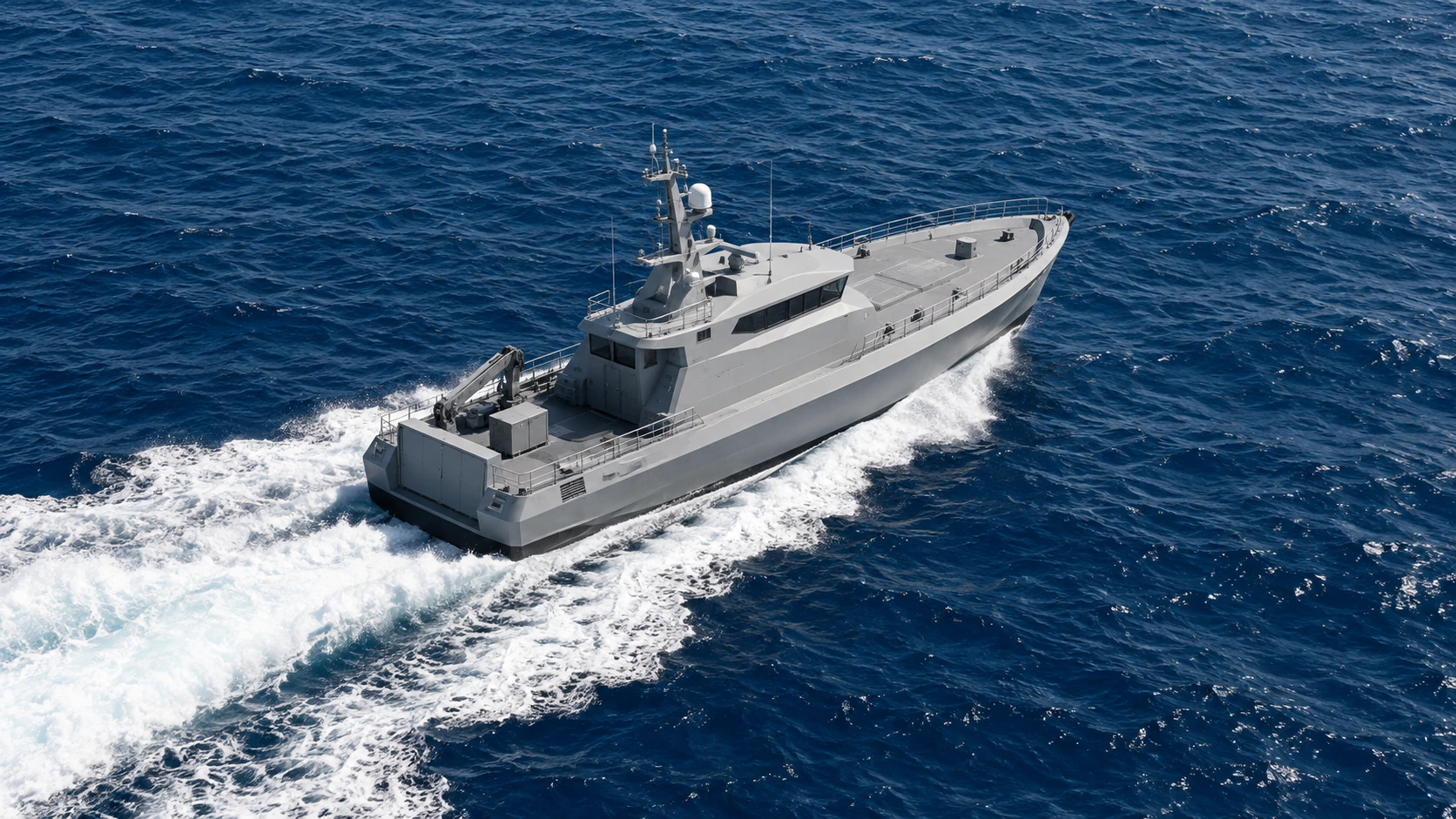
1 The patrol vessel design constraint
The defense prime defined a precise optimization objective to improve the patrol vessel's speed-power performance at the standard half-load condition of 306 tonnes and approximately 2.23-meter draft while preserving the aft hull and propulsion-line arrangement. To minimize disruption to the established vessel architecture, design changes were concentrated in the forward one or two construction blocks.
The design space covered fairing the forward sections, lengthening the hull by two or three frames within a 50-meter overall-length limit, and varying the bulbous bow's length, breadth, depth, and longitudinal position. These changes reshape the vessel's wave system and speed-resistance curve, so each design must be evaluated across multiple operating points rather than at the target speed alone.
The defense prime's existing process sends preliminary lines to an external CFD specialist, reviews a limited number of variants over several weeks, and tests the selected hull in a model basin. The objective of this project was to evaluate a broader range of design variants earlier in the process and reduce the design exploration cycle from months to one or two days before committing CFD and basin-testing resources to the final candidates.
2 Comparison with validated in-house CFD simulations resistance data
Before the defense prime could scale the patrol vessel design search with our Physics AI model, it needed a CFD baseline that reproduced both the resistance trend and the underlying flow physics. Our Simulation Factory orchestrated full-scale calm-water simulations of the fully appended patrol vessel at 3, 9, 15, 21, 25.5, and 27 knots, benchmarked against the defense prime's validated in-house CFD.
The simulations solved the Reynolds-averaged Navier–Stokes equations with the k–ω SST turbulence model and a volume-of-fluid representation of the air-water interface. Two-degree-of-freedom dynamic fluid-body interaction allowed the vessel to settle freely in heave and pitch. The mesh was locally refined around the hull, appendages, free surface, and wake region to resolve the wave system and local pressure gradients. The numerical approach was guided by industry-standard ITTC-recommended practice for grid resolution, convergence, and verification against reference results [1]. The resistance comparison applied the same appendage, wind, and correlation-factor corrections used for the validated in-house CFD reference.
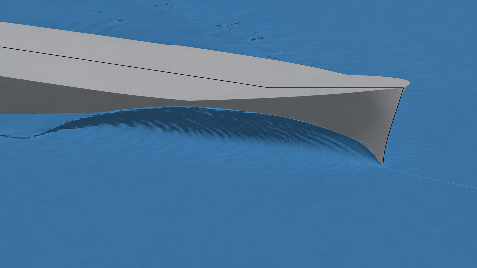
(a) Bow-wave formation at the stem.
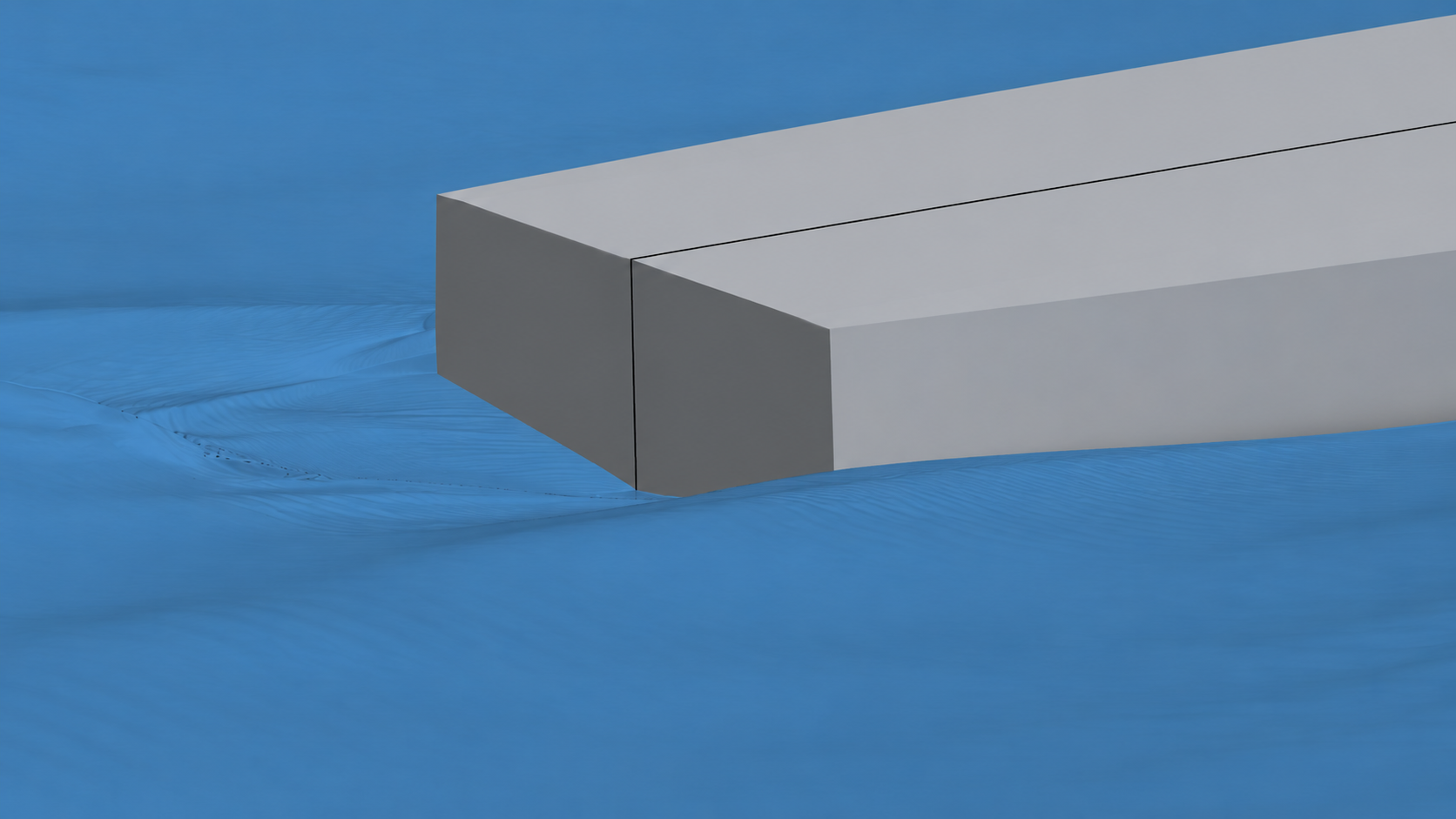
(b) Stern-wave and transom flow.
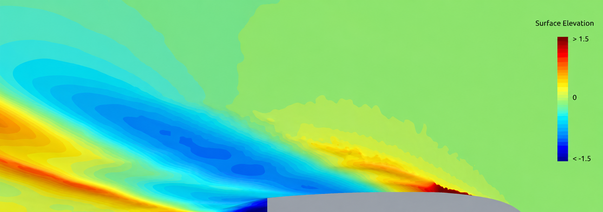
(c) Free-surface elevation showing the Kelvin wave pattern.
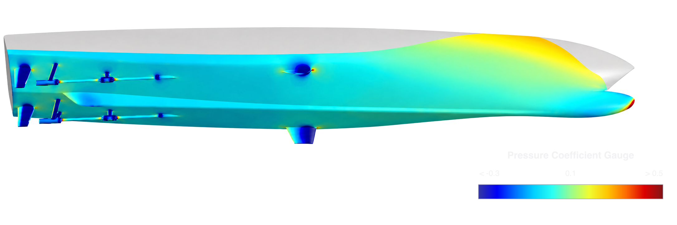
(d) Hull-surface pressure coefficient.
At 27 knots, the solution resolved a well-defined bow crest, the diverging and transverse components of the Kelvin wave system, and clean flow separation at the transom edge. The hull-pressure field showed bow stagnation, acceleration over the forward shoulders, and localized stagnation and suction around the shaft brackets and fin stabilizers. The resulting appendage wakes propagate toward the propeller plane, linking local separation to both resistance and propeller-inflow quality.
Across the six operating points, corrected total resistance differed from the validated in-house CFD reference by a reported mean absolute 2.7% as shown in Figure 3. This CFD-to-CFD correlation established the baseline for the subsequent design comparisons.
With the correlated CFD baseline established, the Simulation Model Factory could turn the defense prime's constrained forebody into the controllable design space described next.
3 A parameterized forebody turns the patrol vessel into a controlled design space
UniversalAGI represented the patrol vessel with more than seventy continuously variable geometry parameters covering hull-form and appendage features. Within the defense prime's design constraints, the parameterization varied the forward fairlines, forebody lengthening, and the bulbous bow's principal dimensions while preserving continuity and fairness across the station sections, waterlines, and buttocks. The aft hull and propulsion-line arrangement remained unchanged. An illustrative workflow is shown in Figure 4.
4 Customizing Ship-PT for the defense prime with our Model Factory
We then used our Model Factory to accelerate design space exploration using Ship-PT. The Model Factory automatically identifies the required simulations and applies uncertainty quantification to ensure a reliable, high-fidelity Ship-PT physics model. Ship-PT is built on UniversalAGI's in-house Latent Interaction Field Transformer (LIFT) architecture [2]. Given a parameterized hull and operating condition, the vessel-specific model returns calm-water total resistance, sinkage, and dynamic trim, together with the corresponding fields of pressure coefficient, wall shear stress, velocity, and water volume fraction.
Ship-PT accepts operating speeds from 3 to 30 knots. The reported median physics-model inference latency was 2.6 seconds on one NVIDIA A100-40GB GPU.
Ship-PT was pre-trained on tens of thousands of calm-water CFD simulation cases. For rigorous evaluation, the most challenging hull geometries were excluded from training at all speeds. The held-out geometries cover central, intermediate, and edge regions of the geometry-parameter ranges. Each held-out geometry was evaluated at three speeds, spanning the entire spectrum from 3 to 30 knots.
5 Ship-PT predicts resistance and flow fields on unseen patrol-vessel hulls
On the final held-out test set, Ship-PT achieved a 5.1% mean absolute percentage error in calm-water total resistance. Beyond this scalar metric, visual comparisons with the corresponding CFD solutions showed that the model reproduced the dominant hydrodynamic features around the hull, including the bow and stern wave crests, Kelvin wake pattern, and major pressure and wall-shear structures. Figure 5 shows two held-out pressure comparisons.
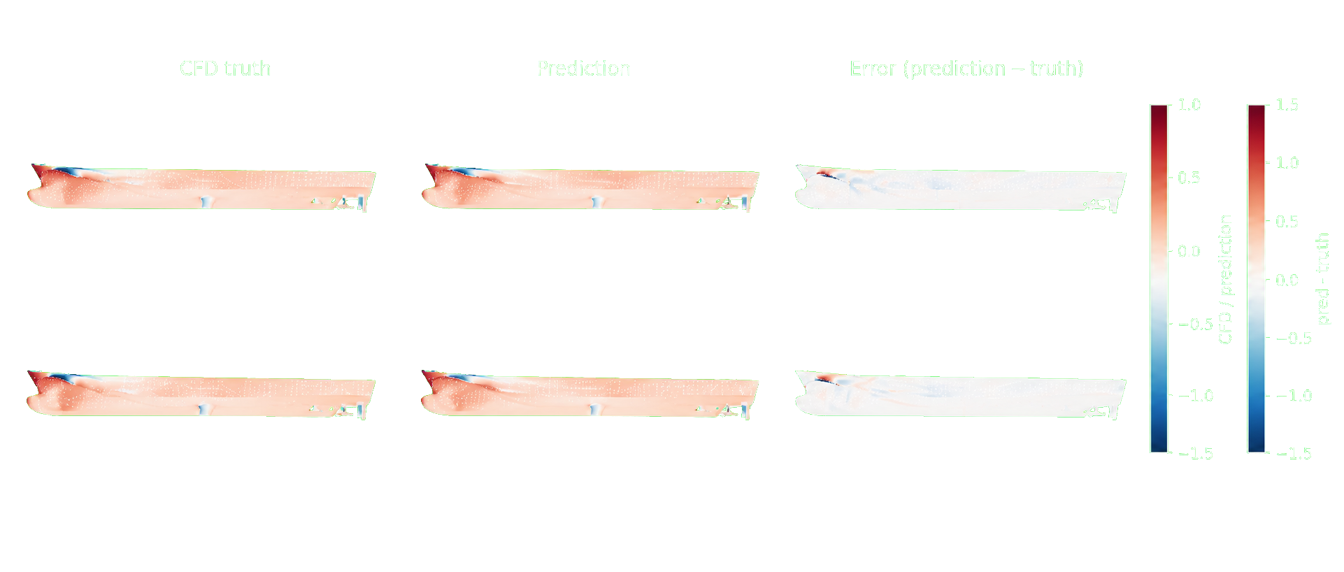
A separate free-surface diagnostic measured a mean absolute error of 0.173 in water volume fraction over faces where the reference value ranged from 0.1 to 0.9. Restricting the calculation to this band focuses the metric on the predicted free-surface pattern around the hull, excluding regions that are fully submerged or entirely above the waterline. Table 1 summarizes the held-out results and inference latency.
| Quantity | Metric | Held-out result |
|---|---|---|
| Calm-water total resistance | MAPE | 5.1% |
| Water volume fraction at the interface | MAE where reference α is 0.1–0.9 | 0.173 |
| Inference latency | Median, 1×A100-40GB; input size and timing scope not reported | 2.6 s |
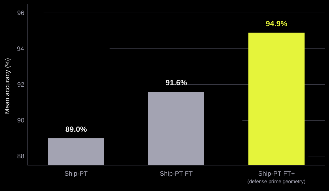
As shown in Figure 6, initial fine-tuning raised mean resistance accuracy from 89.0% for Ship-PT to 91.6% for Ship-PT FT and 94.9% when fine-tuned using our advanced sampling strategy.
6 Ship-PT-guided optimization delivers 5% lower resistance
Fine tuned for the patrol vessel design space using high-fidelity CFD simulations orchestrated by our Simulation Factory, Ship-PT brought Physics AI evaluation into UniversalAGI's advanced design-optimization loop. The workflow explored coordinated changes to the hull form and appendages while preserving the defense prime's constraints on the aft hull, propulsion-line arrangement, and overall vessel architecture.
The optimization produced a better streamlined forebody with a nabla-type (∇) bulbous bow smoothly faired into the hull. At 27 knots, the optimized design reduced corrected total resistance by approximately 5% relative to the current as-built patrol vessel baseline. Figure 8 compares the current as-built patrol vessel baseline with the optimized design, illustrating how the revised forebody fairlines and smoothly integrated bulb reshape the pressure distribution over the forward hull.
(a) No-bulb baseline.
(b) Initial nabla-type bulbous-bow candidate.
7 The defense prime brings real-time hydrodynamics into patrol vessel design
With the parameterized patrol vessel geometry and fine tuned Ship-PT model, the defense prime's naval architects can generate forebody, bulbous-bow, and appendage variants, predict resistance and full hydrodynamic flow fields from low to high Froude numbers, and compare configurations in seconds.
The UniversalAGI platform is directly integrated into the existing workflows for the defense prime's design team. Rather than waiting weeks for each external CFD result, the defense prime can now examine 100x more options within the same project timeline, compare performance across operating conditions, and focus engineering effort on the most promising patrol vessel concepts earlier.
References
- International Towing Tank Conference. (2024). Practical Guidelines for Ship CFD Applications. ITTC Recommended Procedures and Guidelines 7.5-03-02-03, Revision 02. https://ittc.info/media/11958/75-03-02-03.pdf
- UniversalAGI. (2026). SUV-PT architecture benchmark. UniversalAGI Research. https://www.universalagi.com/research/suv-pt