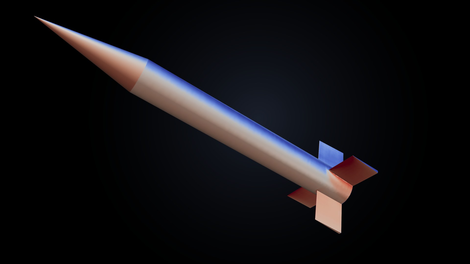
With UniversalAGI's Physics AI, one of the largest defense companies in the world went from a focused set of high-fidelity simulations to projectile aerodynamic data at any condition in the flight envelope.
A projectile's aerodynamic database underpins most analyses of how it flies. Trajectory prediction, stability analysis, and guidance and control design all draw on tables of force and moment coefficients across Mach number and angle of attack, and their results are only as reliable as the data in those tables. The data matter most through the transonic regime and at high angles of attack, where shocks, flow separation, and vortices make the aerodynamics change quickly from one condition to the next.
High-fidelity computational fluid dynamics (CFD) can resolve that behavior, but every combination of Mach number, angle of attack, and configuration is a separate, expensive simulation. A CFD campaign therefore covers a limited set of conditions, and engineers interpolate between them, with no flow solution behind the interpolated values and the greatest risk of error where the aerodynamics change fastest.
UniversalAGI validated a CFD methodology against published wind-tunnel and free-flight data and used it to generate the simulations that fine tune a pretrained physics model. The resulting model can be evaluated at any Mach number and angle of attack in the envelope, for both fin configurations, so the resolution of the aerodynamic database is set by the analysis it feeds rather than by the number of simulations. On CFD cases held out from fine tuning, the model achieved a mean absolute percentage error (MAPE) of 0.78% for the drag coefficient and 1.69% for the lift coefficient .
The defense prime's head of engineering described the effect on its design process:
“This reduces our design cycles from 6–12 months and 7 engineers to 1–3 months with 3 engineers.”
Figure 1 shows the deployed model on the UniversalAGI platform. An engineer selects the fin configuration, Mach number, and angle of attack, and receives the aerodynamic coefficients together with the predicted three-dimensional flow field.
About the geometry: the customer and its proprietary geometries have been anonymized. Because we cannot publish customer geometries, this article uses the publicly available Army-Navy Basic Finner projectile, in its baseline configuration and with its fins canted by 2°, to illustrate the simulation, modeling, and inference capabilities developed during the engagement.
1 Why aerodynamic databases stay sparse
The engagement covered Mach 0.5 to 3.0 and angles of attack from 0° to 55°, for a baseline airframe and a variant with its fins canted by 2°. Across this envelope, the flow passes through substantially different regimes: subsonic flow over the body and fins, the transonic drag rise near Mach 1 where shocks first form, supersonic flow with nose and fin shocks and expansion fans, and crossflow separation with body and fin vortices at high incidence. Each regime changes how the forces and moments respond to Mach number and angle of attack, and the transitions between regimes are where that response is hardest to anticipate.
Semi-empirical methods provide fast estimates, but the transonic regime and high-incidence separated flows are particularly challenging to characterize accurately. High-fidelity CFD captures these regimes, but each condition has to be meshed, solved, checked for convergence, and post-processed. Even a modest resolution of 0.1 in Mach number and 0.1° in angle of attack gives 28,652 conditions across the two configurations, far more than is practical to simulate directly. Engineers therefore simulate a subset of the envelope and interpolate between the simulated points, accepting that the interpolated values carry no flow solution and can miss the nonlinear behavior between those points.
2 Building a trusted high-fidelity physics baseline
A Physics AI model can only be as trustworthy as the simulations it learns from, so the first step was a CFD methodology that holds up across the whole envelope. It has to resolve boundary-layer development, nose and fin shocks, expansion fans, crossflow separation at high incidence, and the projectile wake with one consistent setup.
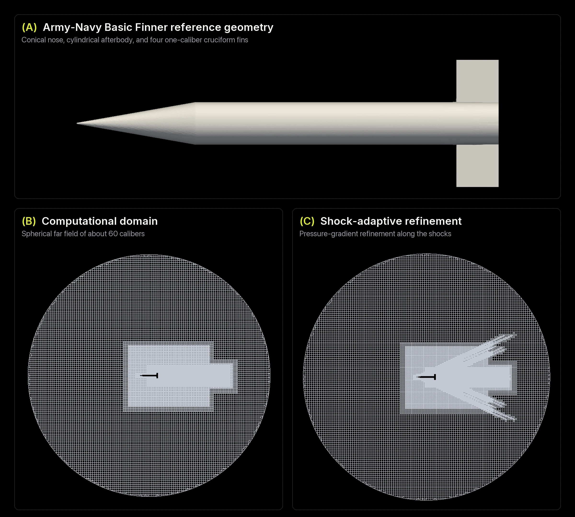
We reconstructed the Army-Navy Basic Finner from its public definition [1]: a conical nose, a cylindrical afterbody, and four one-caliber fins in a cruciform arrangement. The simulations solve the compressible Reynolds-averaged Navier-Stokes equations on wall-resolved meshes, with the first cell at . The mesh is refined adaptively along pressure gradients so the shocks stay sharp at high Mach number, which gives between roughly 13 and 33 million cells for the full projectile, depending on the condition. Figure 2 shows the geometry and mesh.
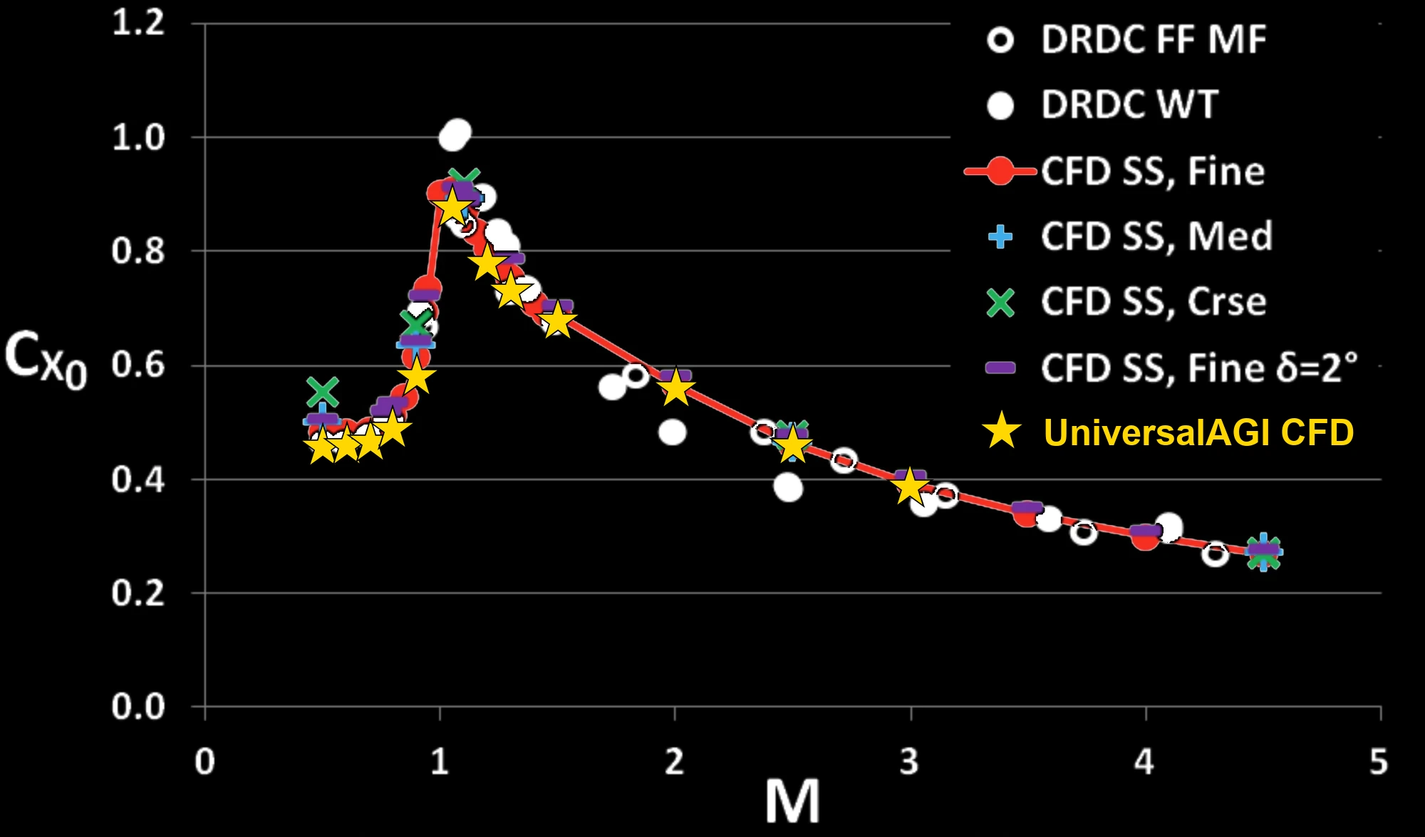
We validated the methodology with a zero-angle-of-attack sweep from Mach 0.5 to 3.0 against the published wind-tunnel, free-flight, and reference CFD data for this geometry [1]. The simulations reproduce the transonic drag rise, which peaks near Mach 1.05, and the decay in drag through the supersonic regime, following the reference CFD and free-flight data closely, as shown in Figure 3. Near Mach 1, the wind-tunnel points sit above both CFD datasets; the reference study notes that simulation and experiment agree least well in this regime.
The published experimental data for this geometry are at zero angle of attack. We therefore carried the validated setup unchanged into the angle-of-attack campaign, so every simulation used to fine tune and evaluate the model shares the same physics, mesh strategy, and numerics.
3 From numerical simulations to a Physics AI model
With the methodology validated, we generated the simulation campaign. Rather than covering the envelope uniformly, our sampling methodology placed more simulations where the aerodynamic response changes most rapidly: the transonic band around Mach 1, where shocks form and drag rises sharply; small angles of attack, which set the normal-force and pitching-moment slopes used in stability analysis; and high angles of attack, where crossflow separation and body and fin vortices make the response increasingly nonlinear. We verified each simulation before training by integrating its processed surface fields and checking the result against the forces reported by the solver.
We used these simulations to fine tune UniversalAGI's pretrained compressible-aerodynamics Physics AI model, which is built on UniversalAGI's in-house Latent Interaction Field Transformer (LIFT) architecture. Because the model is pretrained, the engagement data only has to adapt it to this airframe and envelope rather than teach it aerodynamics from scratch. Mach number and angle of attack are the operating-condition inputs, and the geometry itself defines the configuration.
The second configuration has its fins canted by 2°. On this 300 mm projectile, the cant moves the leading and trailing edges of each fin by about half a millimeter, yet it breaks the roll symmetry of the airframe and produces a rolling moment that spins the projectile in flight. We simulated the canted configuration across the same envelope and fine tuned a single model on both configurations. The model receives no input identifying the configuration. It distinguishes the two from the geometry alone, predicting the rolling moment of the canted fins and essentially none for the baseline.
A separate set of CFD cases on both configurations was withheld from fine tuning and used only for evaluation. The cases span Mach 0.5 to 3.0 across a range of angles of attack. Table 1 reports the result for the final model.
| Quantity | Held-out MAPE |
|---|---|
| Drag coefficient | 0.78% |
| Lift coefficient | 1.69% |
Table 1 measures the model where reference CFD exists. Between simulated conditions, the obvious alternative to a Physics AI model is to interpolate the CFD table. The defense prime tested that alternative in its own evaluation and found the Physics AI model more accurate than interpolation. Instead of drawing curves between tabulated coefficients, the model predicts the flow at each condition and integrates the forces and moments from it.
4 The flow behind every coefficient
The model predicts the underlying surface and volume fields rather than fitting and as independent scalar outputs. The aerodynamic coefficients are calculated by integrating the predicted surface pressure and wall shear stress over the projectile. At each queried condition, the model returns surface pressure and wall shear stress together with the volume pressure, velocity, and density fields. Unlike a value interpolated from a coefficient table, every condition comes with a predicted flow solution that engineers can inspect to understand where the forces and moments come from.
Figure 4 compares the surface pressure at two held-out conditions on the canted configuration. At Mach 1.05 and 20°, the model reproduces the windward compression on the nose and the loading on the fin roots. At Mach 2.5 and 30°, it reproduces the high-pressure windward side of the body and the low-pressure leeward side.
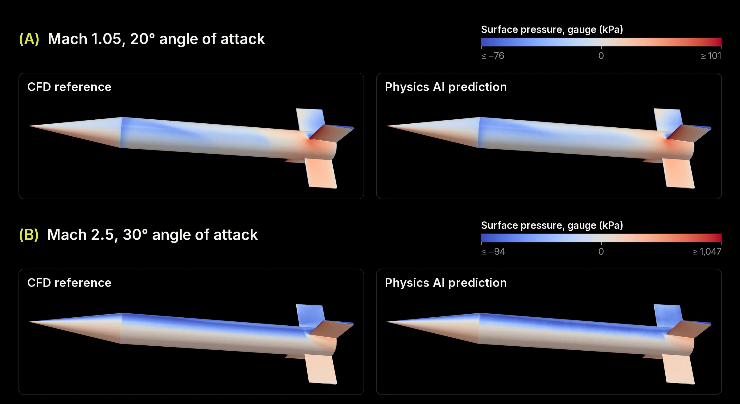
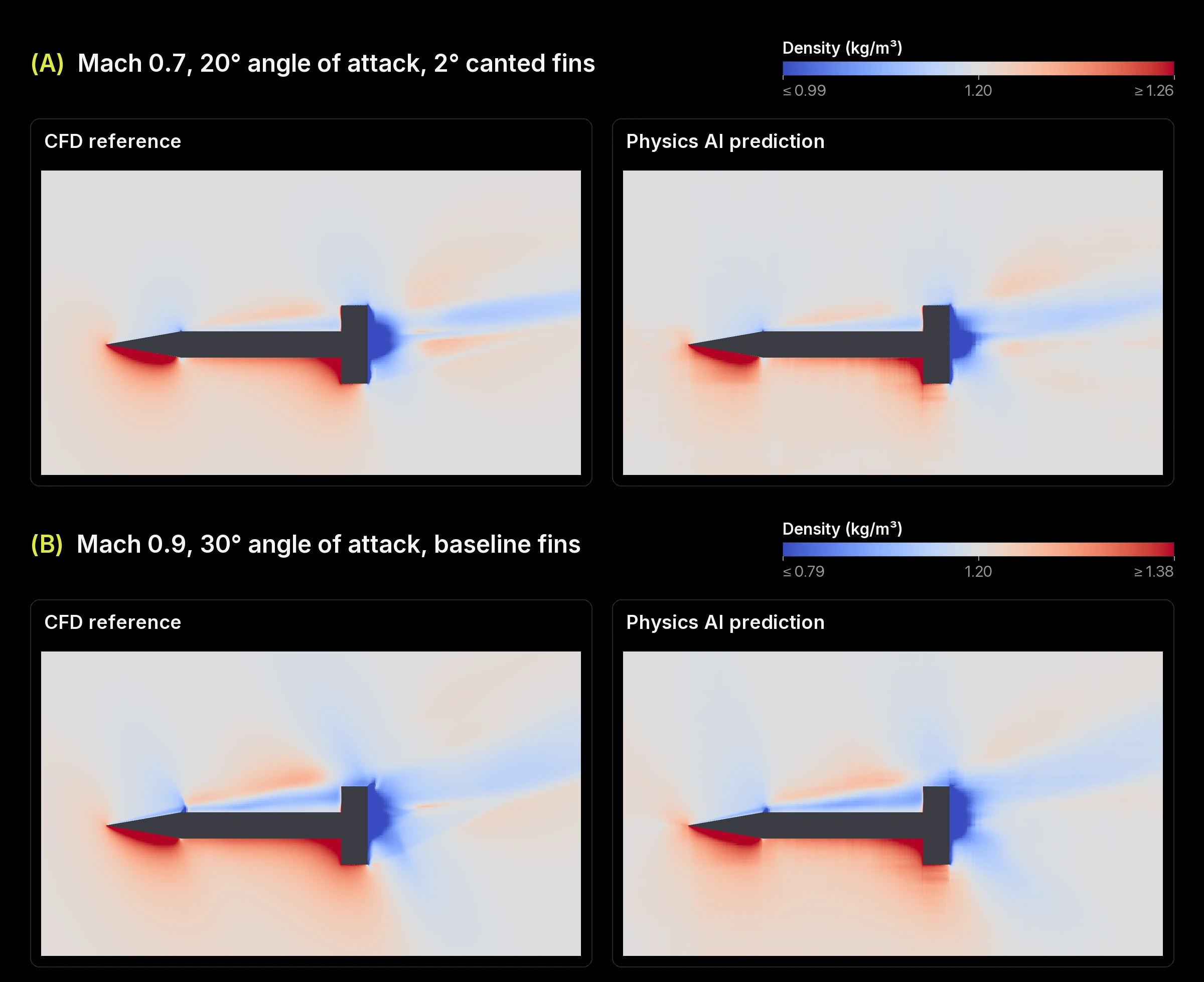
Figure 5 shows the density on the pitch plane at two further held-out conditions. At Mach 0.7 and 20° with canted fins, the model reproduces the compression under the nose and at the windward fin roots, the expansion around the shoulder of the nose, and the low-density region behind the base with the wake trailing to the leeward side. At Mach 0.9 and 30° with baseline fins, it reproduces the windward compression under the nose and fins, the low-density layer along the leeward side of the body with the recompression above it, and the low-density wake behind the base. In each case, the prediction places these structures where the CFD places them.
5 An aerodynamic database at any resolution
With the model fine tuned and evaluated, we used it to generate the aerodynamic database. Because the model can be evaluated at any condition in the envelope, the grid is chosen to suit the downstream analysis. For this engagement, the model was evaluated from Mach 0.5 to 3.0 in increments of 0.1 and from 0° to 55° angle of attack in increments of 0.1°, for both the baseline and the canted-fin configurations, which gives 26 Mach numbers and 551 angles of attack per configuration, or 28,652 conditions in all. A finer grid only means running more inference.
Generating the same database directly with high-fidelity CFD would require a separate simulation at every condition, each of which has to be set up, solved, checked for convergence, and post-processed. With the fine tuned model, the database is a sweep of model inference instead.
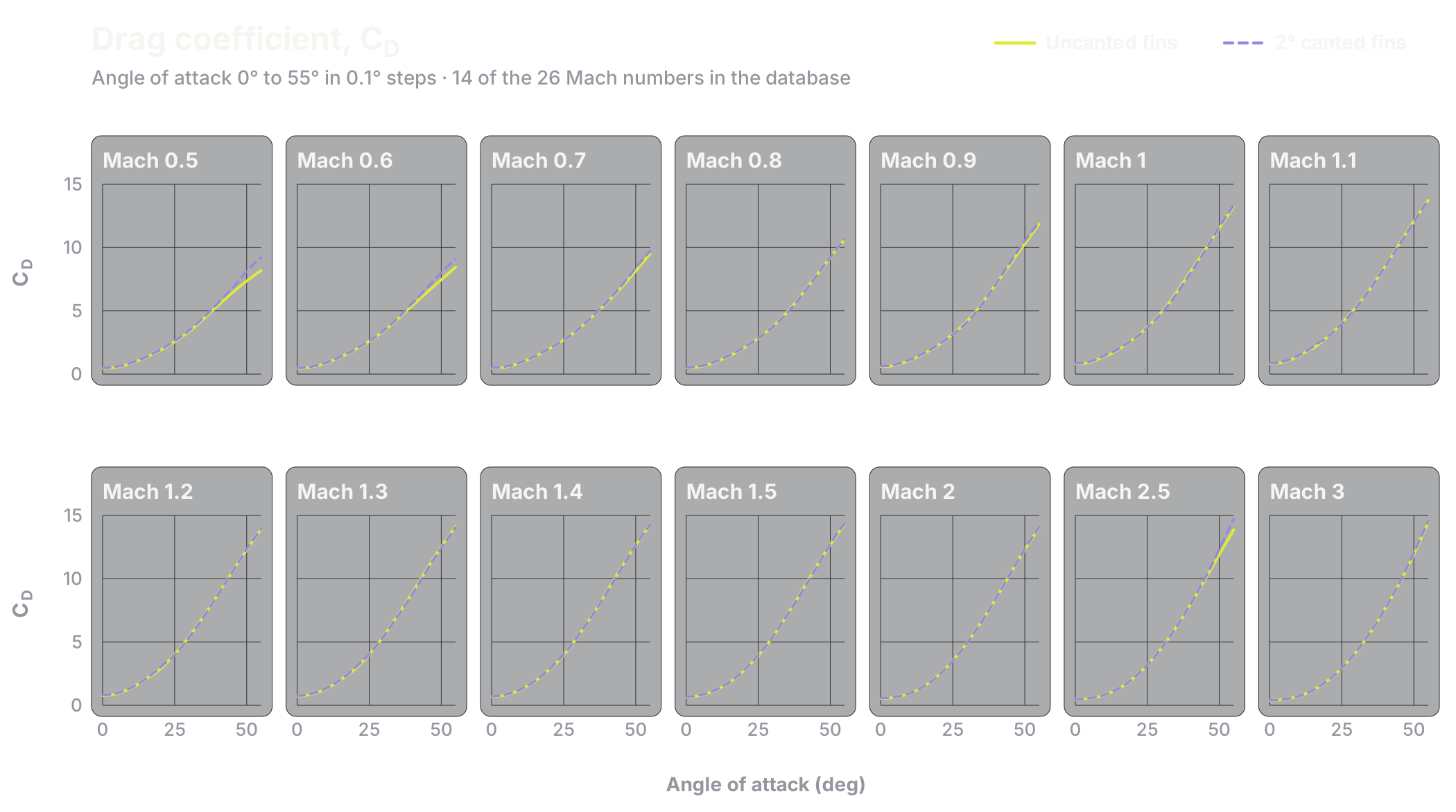
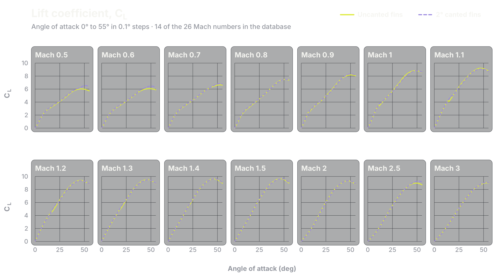
Each condition in the database contains the axial, side, and normal force coefficients; the rolling, pitching, and yawing moment coefficients; drag and lift in wind axes; the center-of-pressure location; and the free-stream state. Figures 6 and 7 plot drag and lift across angle of attack for 14 of the 26 Mach numbers. At this density, engineers can follow how forces and moments evolve through the transonic regime, how they change with incidence, and how a geometry change such as fin cant shifts the response across thousands of conditions.
6 Querying projectile aerodynamics on the UniversalAGI platform
The final model is deployed on the UniversalAGI platform, so engineers can query conditions directly rather than working only from a fixed database. A user specifies the fin configuration, Mach number, and angle of attack and runs inference, as in Figure 1. The platform returns the aerodynamic coefficients and displays the predicted surface and volume fields for interactive inspection. Conditions between the database grid points can be queried the same way.
The same model supports parameter sweeps. Figure 8 shows a sweep of 26 Mach numbers at zero angle of attack: the predicted fields at two conditions are compared side by side, and the axial-force coefficient is plotted against Mach number. A dense database can feed downstream flight-dynamics or system analysis, while an engineer investigating one flight condition can request the corresponding three-dimensional flow solution.
Highlights
- UniversalAGI worked with one of the largest defense companies in the world to bring Physics AI into projectile aerodynamic characterization.
- The CFD methodology was validated against published wind-tunnel, free-flight, and reference CFD data for the Army-Navy Basic Finner from Mach 0.5 to 3.0.
- The fine tuned model can be evaluated at any Mach number and angle of attack in the envelope. For this engagement, it generated a database at 0.1 Mach and 0.1° angle-of-attack resolution, a density that would be impractical to reach with CFD alone.
- In the defense prime's own evaluation, the model was more accurate than interpolating the CFD table.
- On CFD cases held out from fine tuning, the model achieved 0.78% MAPE for and 1.69% MAPE for .
- A single set of weights covers Mach 0.5 to 3.0, angles of attack from 0° to 55°, and both the baseline and 2° canted-fin configurations, which the model distinguishes from the geometry alone.
- Every coefficient is integrated from the predicted surface pressure and wall shear stress, and the surface and volume fields are available on the UniversalAGI platform at any condition in the envelope.
Increasing the resolution of aerodynamic data
High-fidelity CFD remains the foundation of this workflow. It provides the validated simulations used to fine tune and evaluate the model. Running another high-fidelity simulation for each point of interest, however, makes dense exploration of an envelope expensive.
A fine tuned physics model changes that tradeoff. A targeted simulation campaign fine tunes a model that can then be evaluated at as many conditions as an analysis requires, while returning the surface and volume fields that engineers use to understand the underlying aerodynamics. For this engagement, that meant going from a focused set of CFD simulations to a database at 0.1 Mach and 0.1° resolution across the projectile operating envelope, with any condition between the grid points available on demand. As a design evolves, the model can be updated with additional simulations to cover new configurations.
If simulation cost limits how densely you can characterize your designs, talk to a UniversalAGI engineer.
References
- V. A. Bhagwandin and J. Sahu, Numerical Prediction of Pitch Damping Stability Derivatives for Finned Projectiles, Technical Report ARL-TR-6725, U.S. Army Research Laboratory, Aberdeen Proving Ground, MD, 2013.