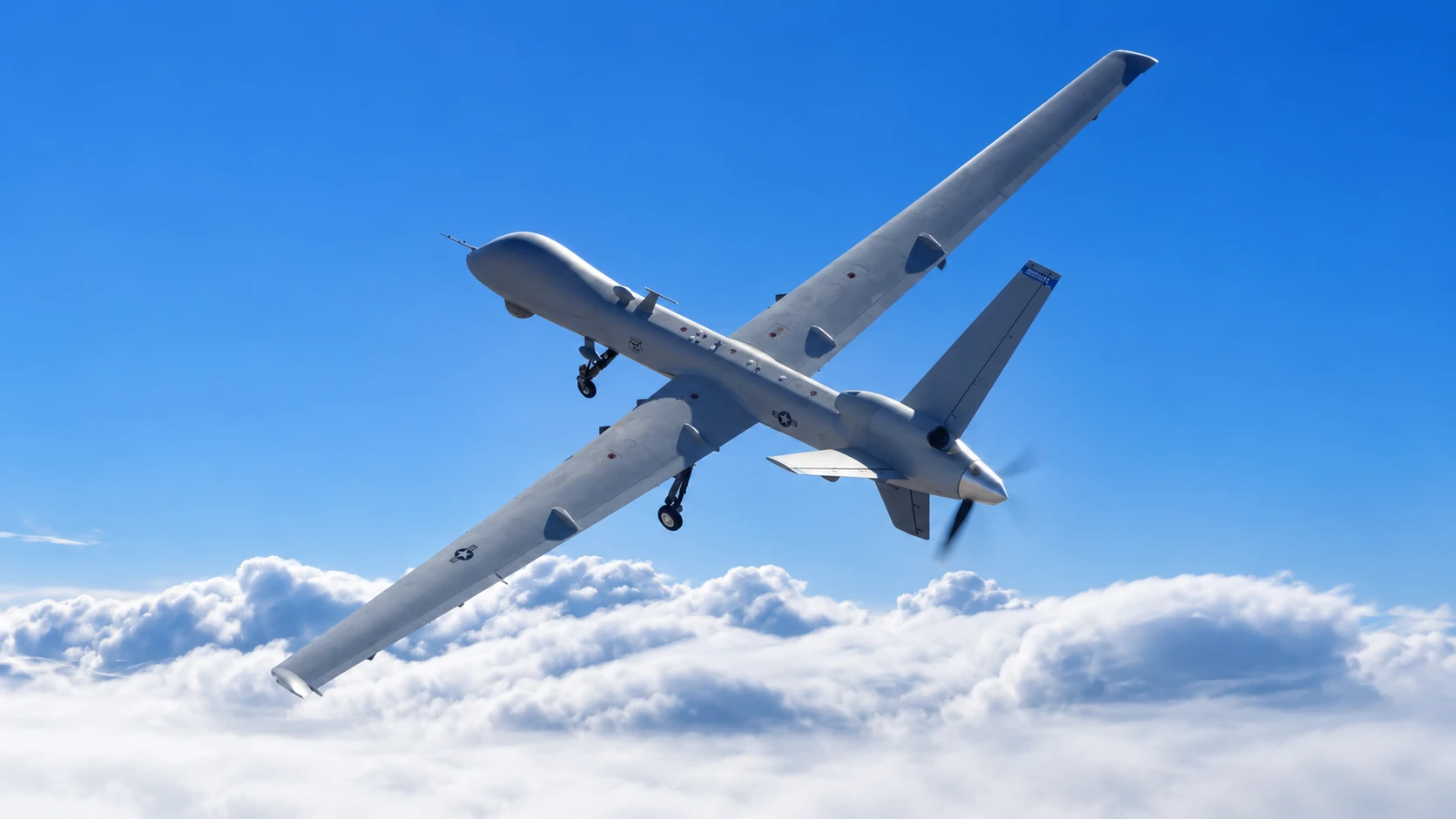
A defense prime uses UniversalAGI's Physics AI model to investigate its fixed-wing drone across the flight envelope in seconds instead of waiting days for each CFD simulation.
The defense prime is advancing low-altitude airspace protection with a rapid-response fixed-wing interceptor. Bringing that airframe from concept to flight requires high-confidence aerodynamic characterization long before a physical prototype leaves the ground. Engineers need to understand lift and drag, stability, stall, sideslip behavior, and control authority across the intended flight envelope.
To keep pace with its rapid airframe development, the defense prime needed faster aerodynamic characterization. In a conventional computational fluid dynamics (CFD) campaign, every combination of velocity, angle of attack, sideslip, and control-surface deflection becomes a separate case. Engineers must set up, solve, check, and post-process each case. Repeating this process across the flight envelope consumes significant compute and can take weeks.
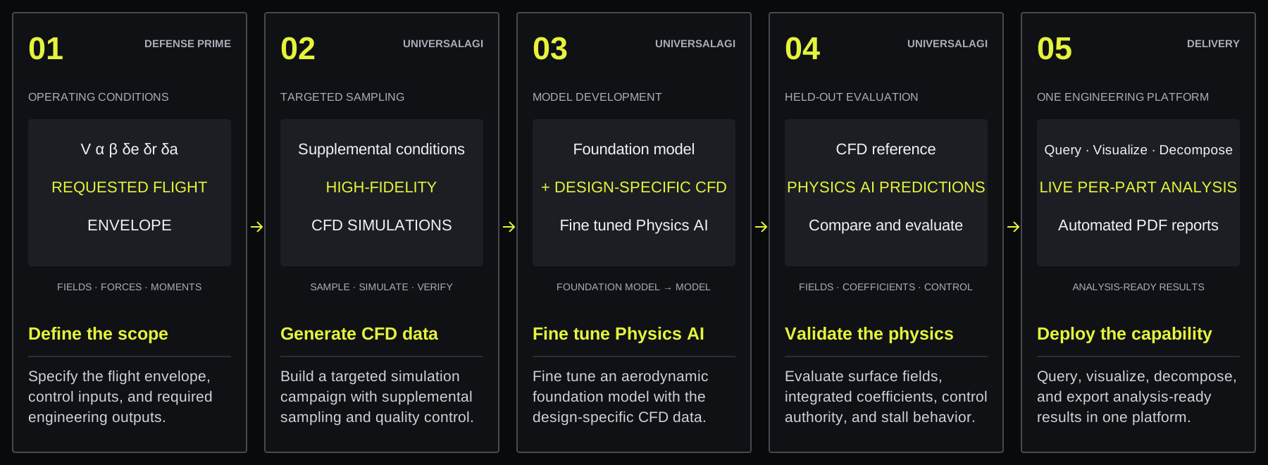
UniversalAGI used a small set of high-fidelity simulations to customize Drone-PT, a physics model for the defense prime’s airframe. The fine tuned model reached 95% accuracy on integrated aerodynamic coefficients. The defense prime can now evaluate a new condition in seconds, investigate flight and control inputs at a finer resolution than the original CFD campaign, and automatically convert parameter sweeps into engineering plots, derived metrics, and a technical PDF report. Figure 1 shows this workflow on the UniversalAGI platform.
1 The Combinatorial Cost of CFD-based Envelope Coverage
The central challenge was covering the requested multidimensional flight envelope. Control effectiveness varies with the operating conditions, while the aerodynamic response becomes increasingly nonlinear near separation and stall. Sweeps across individual input variables therefore capture only part of the aerodynamic behavior the defense prime needed to characterize.
Resolving every variable at useful increments causes the number of CFD cases to grow rapidly. Each case must be simulated, checked for convergence, post-processed, integrated into forces and moments, and incorporated into the analysis. This limits the coverage achievable within a conventional CFD campaign.
The defense prime also worked on a compressed development timeline that could not accommodate a lengthy CFD campaign. The characterization still required high-fidelity results near stall and for stability and control authority.
2 Customizing the Drone-PT Foundation Model for the defense prime
Our approach started from an aerodynamic foundation model trained on tens of thousands of CFD simulations across a broad range of geometries and operating conditions. We then fine tuned Drone-PT with a limited amount of high-fidelity, design-specific CFD data to capture the aerodynamic behavior of the defense prime’s airframe.
The defense prime defined the required flight envelope and engineering outputs. We translated this scope into a targeted campaign that generated a small set of high-fidelity CFD simulations. In addition to the baseline sweeps, we selected supplemental conditions to cover the parameter space and combined inputs that the model would encounter during evaluation.
The input space included velocity, angle of attack, sideslip, and independent control-surface deflections. The model predicted surface pressure and wall shear stress distributions. The platform integrated these fields over the airframe to calculate aerodynamic forces and moments, maintaining consistency between the predicted fields and the resulting integrated quantities.
The platform then derived the required engineering metrics, including lift and drag coefficients, pitching, rolling, and yawing moments, stability derivatives, stall angles and velocity, control-surface effectiveness, hinge moments, and force and moment decomposition by airframe component. Figure 2 summarizes the complete workflow from product scoping through model customization and deployment.
3 Building a High-Quality CFD Dataset
Model accuracy is bounded by the quality and coverage of its reference data. We therefore treated CFD data generation and model development as one connected workflow.
The customer-requested operating conditions established the principal flight and control-surface sweeps. We supplemented these cases with a targeted sampling plan designed to cover gaps between the discrete sweeps, combined control inputs, sideslip away from the primary operating points, and physically important regions such as the onset of stall. The resulting dataset supported a continuous model response over the requested domain, including conditions between the original CFD points.
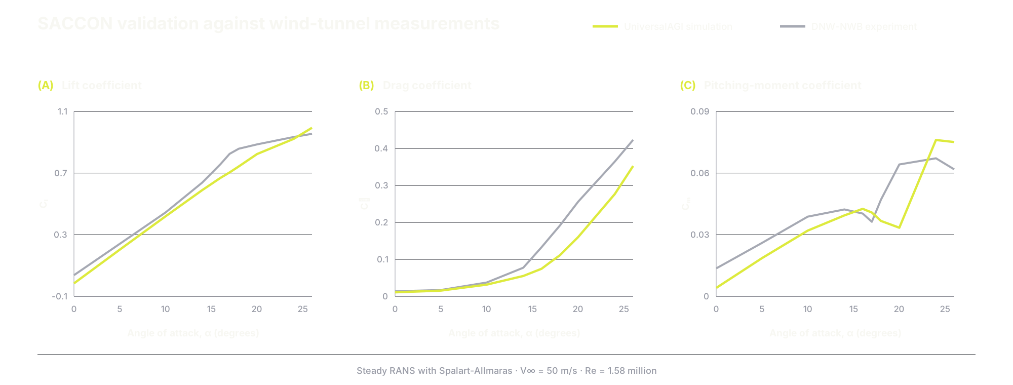
The reference data came from high-fidelity, wall-resolved steady RANS simulations with approximately 30 to 50 million polyhedral cells per case. The mesh was sufficiently refined around the leading edge to capture vortex formation according to published best practices, with prism layers maintaining across the airframe. The Spalart-Allmaras turbulence model was selected after validation against SACCON, a public swept-wing reference configuration. The validated setup agreed closely with published wind-tunnel and CFD data for lift and reproduced the characteristic pitching-moment behavior of delta-wing drones created by the evolving vortex system [1], [2].
Each aerodynamic solution passed through the same validated simulation pipeline for geometry preparation, meshing, numerical solution, convergence, and post-processing. Every production case converged to within 0.2% on forces and moments. Appendix A1 describes the numerical setup, mesh-independence study, quality controls, and SACCON validation in detail. Figure 3 presents one representative result from this production dataset.
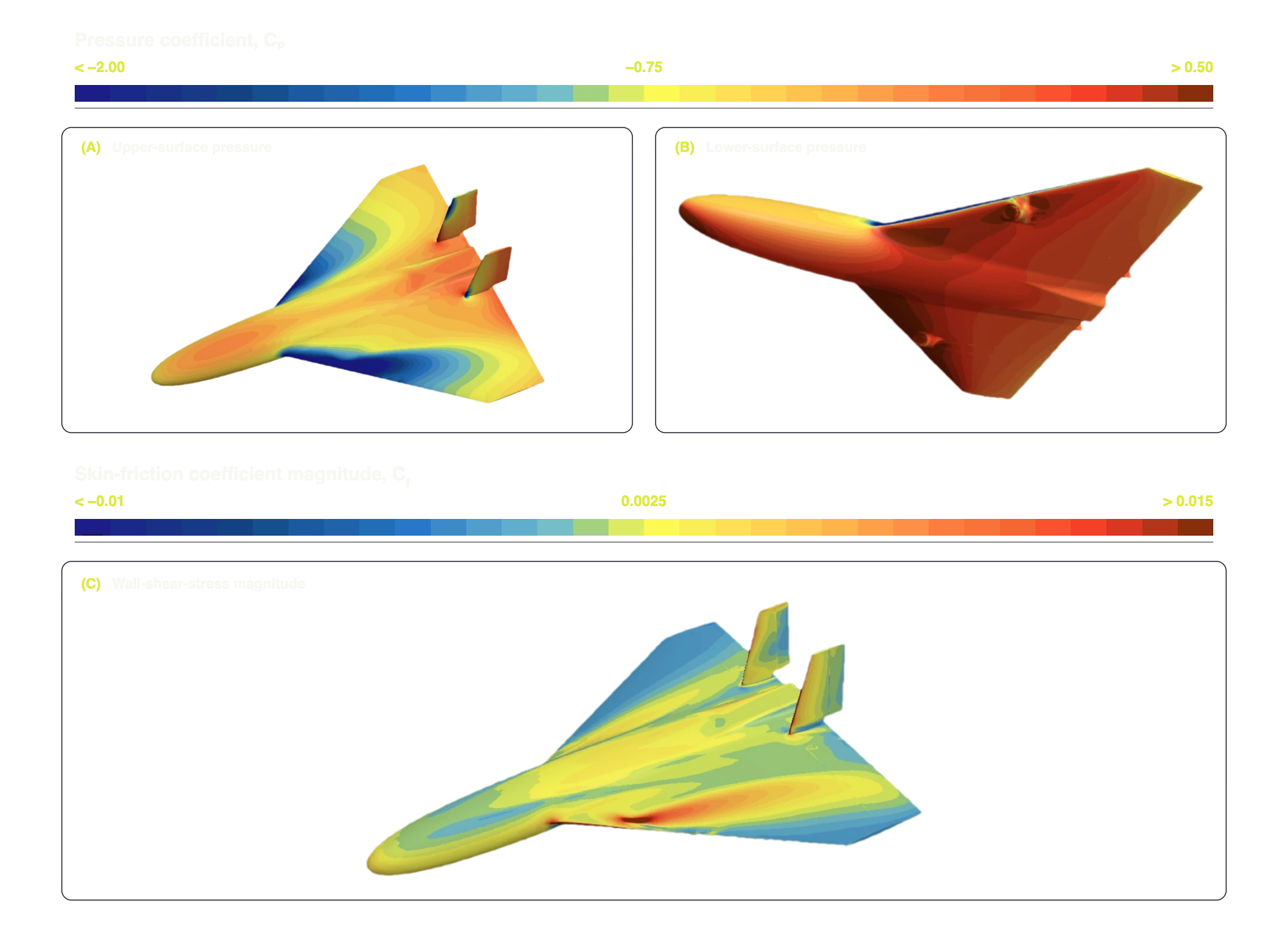
This representative case shows the three-dimensional physics that the dataset captures. Strong suction develops over the forward fuselage and inboard wing as the flow accelerates over the blended wing-body profile. A stagnation region forms on the lower surface near the nose and leading edge. Sideslip produces asymmetric pressure loading and wall shear stress across the two wings. Capturing these coupled pressure, viscous, and vortex-driven effects is essential for predicting forces, moments, stability, and control authority across the flight envelope.
4 Benchmarking Must Cover Critical Flight Conditions
Aggregate metrics can conceal localized weaknesses under specific operating conditions. Customizing Drone-PT with design-specific CFD data enabled the model to capture the airframe’s design-specific aerodynamic behavior. We then evaluated the fine tuned model across distinct parts of the flight envelope, focusing on stability-critical, control-critical, and near-stall conditions.
The final evaluation used CFD cases that were held out from training. The benchmark was stratified across the requested envelope and grouped by engineering difficulty. It included baseline operating conditions, combined control-surface deflections, difficult angle-of-attack conditions, and sideslip sweeps. Appendix A2 describes the benchmark design.
Across this benchmark, the model achieved a mean absolute percentage error (MAPE) of 4.38% on the drag area and 2.18% on the lift area . The median absolute percentage errors were 1.20% and 0.77%, respectively. The mean includes the difficult cases across the full benchmark and the median describes the error on a typical evaluation. Table 1 summarizes these results, and Appendix A3 defines the metrics.
| Evaluation target | Metric | Result |
|---|---|---|
| Drag area | MAPE | 4.38% |
| Drag area | median APE | 1.20% |
| Lift area | MAPE | 2.18% |
| Lift area | median APE | 0.77% |
| Surface pressure | relative L2 error | 5.74% |
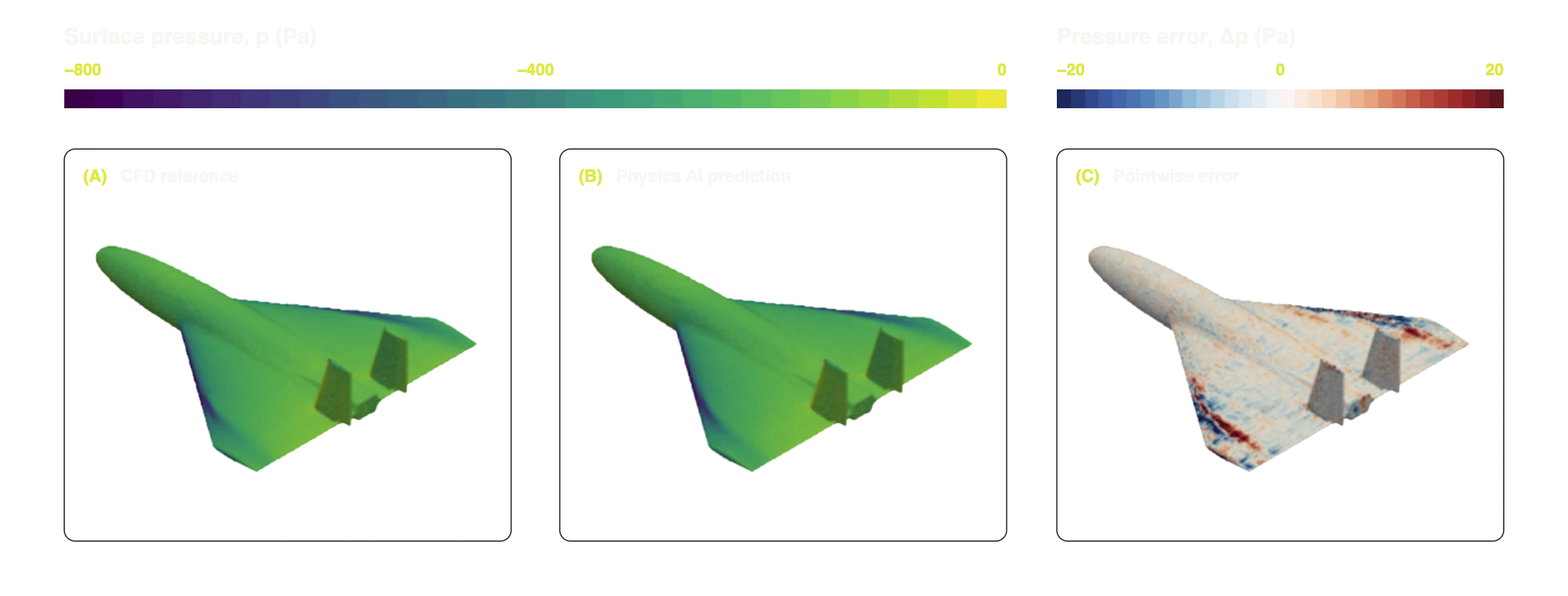
We also evaluated the predicted surface pressure field directly and measured a relative L2 error of 5.74%. This field-level evaluation guarded against local prediction errors cancelling out in the integrated force metrics. It also showed that the model reproduced the underlying flow field, as shown in Figure 4.
Control authority was evaluated through the slopes of the aerodynamic response to control deflection. The predicted moment-coefficient slopes were 96% of the CFD reference for elevator pitch, 98% for aileron roll, and 99% for rudder yaw.
Stall velocity and stall angles define the low-speed boundary of the flight envelope and the upper limit for the angle of attack, respectively. Accurate values are required for the defense prime to define the operating margins. Across the evaluated sweeps, the predicted stall angles and derived stall velocity agreed with the CFD reference to within 5%. This is especially relevant because stall is both flight-critical and difficult to predict, with flow separation producing strongly nonlinear aerodynamic behavior.
A senior algorithms and systems engineer at the defense prime said after reviewing the stall characterization:
“It's exactly what I've calculated from the CFD data.”
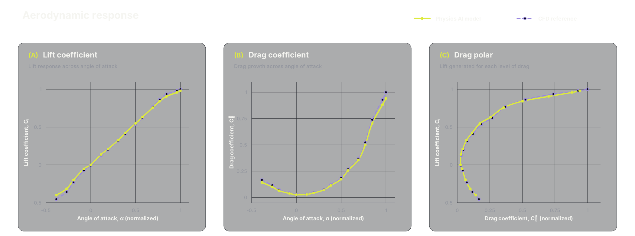
To evaluate the model's global aerodynamic response across the angle-of-attack range, we compared the predicted lift and drag curves and drag polar with the CFD reference. Figure 5 shows that the model reproduced the aerodynamic behavior across the evaluated range.
5 Deploying Physics AI as an Automated Engineering Workflow
The deployed model is integrated into the UniversalAGI platform, providing the complete engineering analysis workflow. The defense prime defines a parameter sweep, and the platform evaluates the requested conditions, integrates the surface predictions, calculates the relevant metrics, and generates the plots and tables. This covers lift curves, drag polars, stall analysis, and stability derivatives including sideslip conditions, as well as control-authority analysis and hinge moments for deflected control surfaces.
Forces and moments can also be inspected and differentiated by airframe component. This reveals how the wing, fuselage, tail, and control surfaces contribute to drag, trim, stability, and control authority, even when their contributions cancel in the global coefficients for the airframe. The defense prime can explore this decomposition interactively on the platform and use it to focus subsequent design changes.
Fine sweeps can be generated for particularly relevant flight regimes, such as near-stall or around a specific control setting. Results are available interactively through the platform and as an automatically generated PDF report, as shown in Figure 6. The platform integration removes much of the repetitive work of a conventional CFD workflow. The defense prime can investigate new conditions without configuring and monitoring additional simulation cases, post-processing raw results, and rebuilding plots for each analysis.
6 Integrating Physics AI into a Defense Prime’s Aerodynamic Design
The delivered Physics AI model combines fast evaluation, continuous coverage of the requested flight envelope, and direct integration into the UniversalAGI platform. The defense prime can evaluate individual conditions in seconds, query combinations of operating conditions, and obtain engineering outputs directly.
For the defense prime, this means:
- More detailed aerodynamic characterization. The defense prime can evaluate flight conditions at a finer granularity than would be practical with conventional CFD and examine the rapidly changing airframe response near stall or around specific control settings.
- Access to combined flight and control conditions. The defense prime can investigate multiple control-surface deflections at different velocities, angles of attack, and sideslip angles. Covering these combinations systematically would have been impractical with conventional CFD.
- Less manual engineering work. The platform provides aerodynamic coefficients and plots, interactive force and moment decomposition by airframe component, and an automated report. The defense prime can work directly with the aerodynamic results without the manual workload associated with a conventional CFD workflow.
As the airframe evolves, the model can be updated with additional data to support further design iterations. The same approach can be applied to design-space exploration and aerodynamic optimization.
To learn more about the foundation model and LIFT approach behind our aerodynamic work, read SUV-PT: Physics Transformer for SUVs. If simulation limits your engineering workflow, talk to a UniversalAGI engineer.
Appendix
A1 CFD setup and validation
A1.1 Physics and solver setup
The CFD campaign resolved the detailed aerodynamic behavior of the defense prime’s airframe. We ran steady-state, incompressible simulations with wall-resolved Spalart-Allmaras turbulence modeling, selected and validated through the SACCON benchmark described below. The computational domain was extended far enough from the airframe to make the solution independent of the far-field boundaries.
All production cases used the same experimentally benchmarked and mesh-independent setup described in the following sections.
The results met a strict numerical quality bar. Integrated forces and moments converged to within 0.2% over the final iterations, while independent monitors confirmed stable aerodynamic coefficients and physically consistent surface fields. These controls ensured the high fidelity of the simulations used to customize our Drone-PT model.
A1.2 Meshing strategy and mesh independence
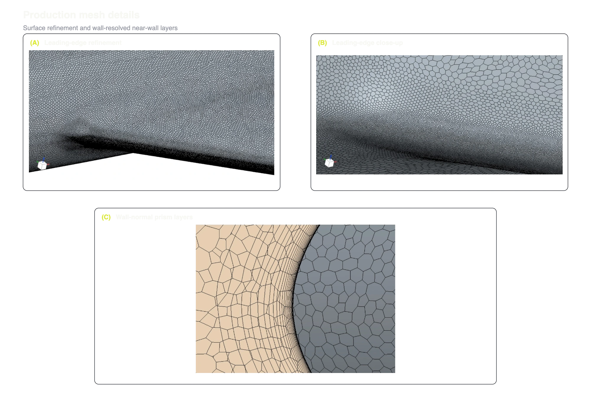
The production meshes contained approximately 30 to 50 million polyhedral cells per case. Leading-edge refinement provided 30 to over 50 cells across the contour, following published best practices for resolving the apex and tip vortices that govern this low-aspect-ratio, highly swept configuration. Prism layers maintained across the airframe, resolving the viscous sublayer without wall functions. Adaptive mesh-refinement strategies further refined the vortex-forming and near-wall regions, improving the resolution of vortex development and boundary-layer behavior.
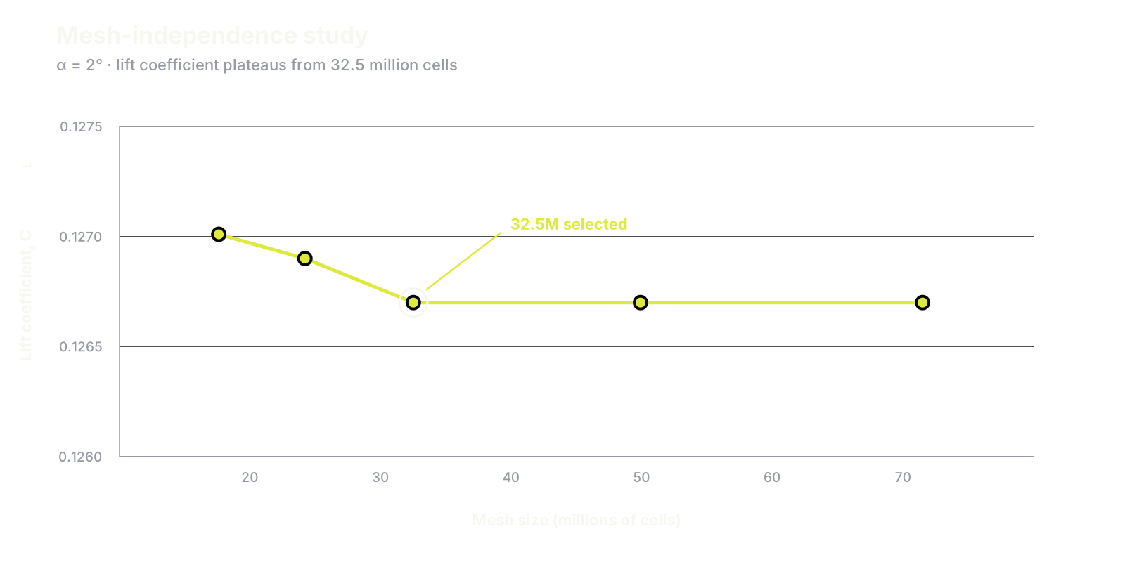
An initial mesh-independence study evaluated five meshes from 17.6 million to 71.5 million cells at . The lift coefficient changed from 0.12701 on the coarsest mesh to 0.12670 at 32.5 million cells, then remained unchanged through the 49.9 million and 71.5 million-cell meshes. This plateau, shown in Figure A1, supported the 30 to 50 million-cell production range. Details of one representative production mesh are shown in Figure A2.
A1.3 Validation against the SACCON benchmark
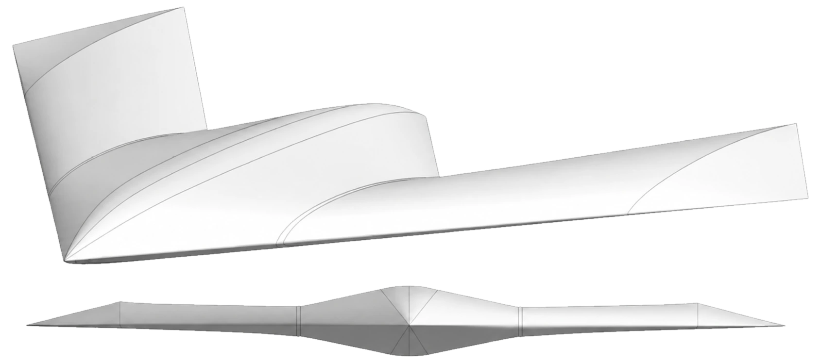
Before applying the production setup to the defense prime’s airframe, we validated the CFD methodology on the public SACCON Stability and Control Configuration, as shown in Figure A3. SACCON is a 53-degree-swept, low-aspect-ratio UCAV reference geometry developed under NATO/RTO AVT-161 [2] and tested at DNW-NWB and NASA Langley [1]. Its blended planform, vortex-dominated flow, and published force, moment, and surface-pressure measurements make it a relevant benchmark for the defense prime’s configuration.
The final validation campaign used steady-state RANS simulations at m/s, , , and angles of attack from to . The validation program evaluated the – SST transition model and Spalart-Allmaras. Spalart-Allmaras agreed more closely with the published reference data, so we selected it for the defense prime’s production simulations. Figure A4 compares the resulting aerodynamic coefficients with the published wind-tunnel measurements.
We also inspected the surface-pressure and wall-shear-stress fields to confirm that the simulation reproduced the relevant vortex footprints and near-wall flow structure, as shown in Figure A5.
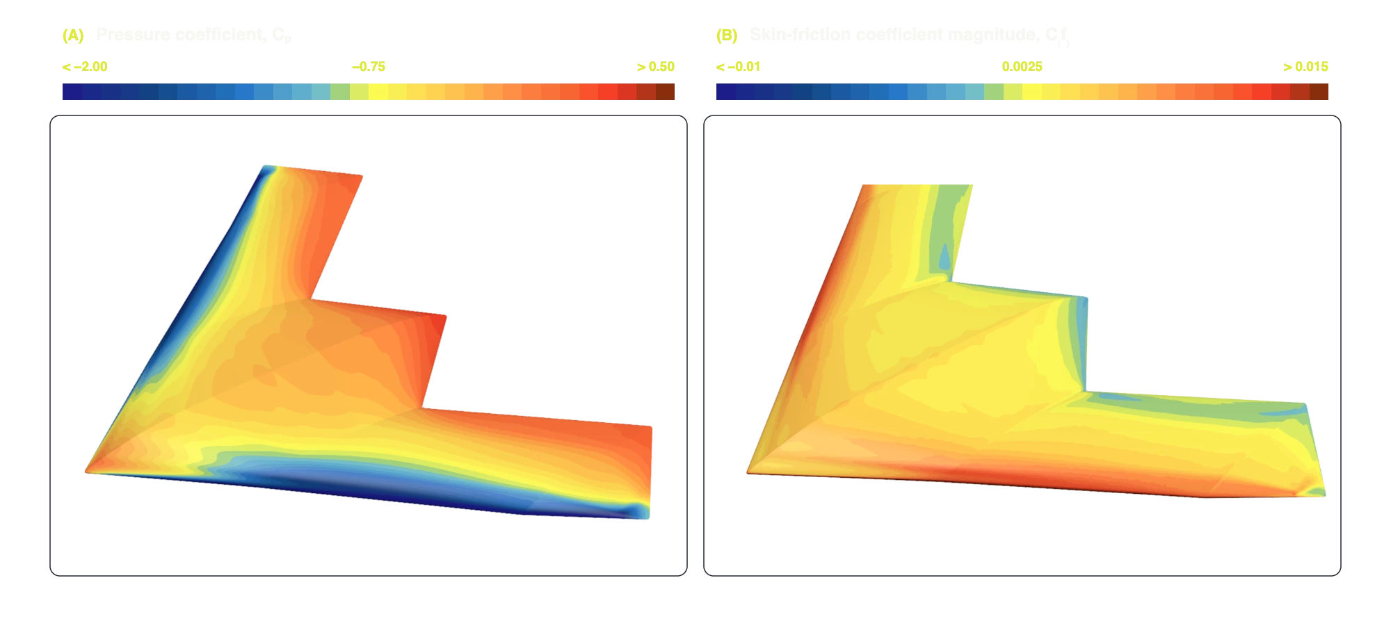
The validation reproduced the lift-curve trend from the linear into the nonlinear regime at high angles of attack and captured the characteristic rise and dip in pitching moment as the apex and tip vortices evolved. Where the steady simulations deviated from the experimental measurements at the highest angles of attack, the results remained close to the published steady-CFD results in [2] and reproduced the same vortex-topology-driven pitching-moment behavior. This agreement across the integral coefficients and surface-field topology established the final turbulence model and mesh configuration used for the defense prime’s production campaign.
A2 Benchmark design
The benchmark contains numerous CFD cases that were held out from model training. Cases were selected before the final model evaluation and grouped into four blocks:
- Requested-scope fidelity: baseline flight conditions and individual control-surface sweeps from the requested aerodynamic characterization matrix.
- Combined control inputs: cases in the interior of the multi-surface deflection space, where multiple controls are active simultaneously.
- Angle-of-attack extremes and off-grid conditions: difficult incidence conditions and velocities away from the principal training sweeps.
- Sideslip variation: zero- and higher-sideslip conditions distributed across the operating domain.
This structure prevents nominal cases from dominating the reported result and tests both interpolation between sampled conditions and generalization away from the discrete CFD sweeps.
A3 Evaluation metrics
Let be the CFD reference value for case , be the model prediction, and be the number of benchmark cases.
Mean absolute percentage error (MAPE; lower is better) measures average relative error. We report it for and :
Median absolute percentage error (median APE; lower is better) describes the error on the median case and is less sensitive to a small number of particularly difficult operating conditions:
For surface pressure, let and denote the CFD and predicted fields for case . We calculate the relative L2 error over the surface and then average it across the benchmark:
Control authority is evaluated using the control-effectiveness derivative , obtained from a linear fit across each dedicated control-surface sweep. We report the model-to-CFD ratio:
The relevant derivatives are for elevator pitch, for aileron roll, and for rudder yaw. A value of 100% indicates agreement with the CFD control derivative.
References
- T. Loeser, D. D. Vicroy, and A. Schütte, “SACCON Static Wind Tunnel Tests at DNW-NWB and 14′ × 22′ NASA LaRC,” 28th AIAA Applied Aerodynamics Conference, AIAA Paper 2010-4393, 2010.
- A. Schütte, D. Hummel, and S. M. Hitzel, “Numerical and Experimental Analyses of the Vortical Flow Around the SACCON Configuration,” 28th AIAA Applied Aerodynamics Conference, AIAA Paper 2010-4690, 2010.